1. Product modeling analysis & equipment assembly analysis:
The parts of 155 products include:

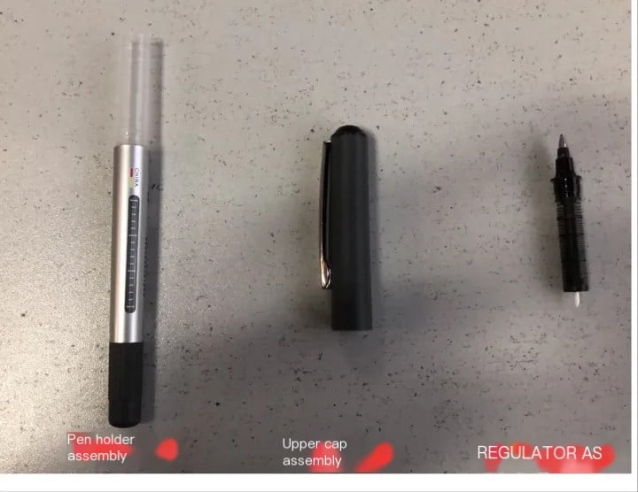
●Upper cap assembly, including upper cap, pen clip, inner cap, upper plug Pen barrel assembly, including pen barrel, tail plug, and printing (transfer process) of the pen barrel Adjuster assembly, including adjuster, pen head assembly, large Front head Pen head assembly, including pen head and relay core Ink analysis of these parts and components, first judge whether all parts can be assembled by one device, obviously, the components of the 155 product are complex, for example, the upper cap assembly needs to be vertical Equipment assembly, and the printing requirements of the pen holder assembly require horizontal equipment assembly, the assembly process is very different, and the number of parts is large, it is impossible to realize the assembly of all parts on one equipment, and it needs to be assembled by equipment. According to the characteristics of the components, there are required The combination of four sets of equipment completes the final assembly of the product, including cap assembly machine, pen holder assembly machine, nib assembly machine, and pen assembly machine. 2. Equipment assembly process design: 2.1 The main frame of the equipment: The design of the main frame of the equipment determines the key performance indicators such as the speed and beat of the equipment. If the manufacturing of automated assembly equipment is likened to building a house, the main frame of the equipment can be understood as laying the foundation. The structure and quality of the frame determine the life and performance of the equipment. The equipment frames of 155 series products including other Baixue products are all welded by high-strength and large-thickness steel plates. This structure is different from ordinary aluminum profile frames. It features heavy weight and stable chassis, which can meet the high-speed operation of the equipment. A high-quality frame only satisfies the static state of the equipment, and a high-precision motion system is required to satisfy the dynamic state of the equipment. Due to the assembly requirements, the motion system of the assembly machine needs to have intermittent pauses during the motion process. The position accuracy of the pause determines the accuracy of the assembly. Accuracy, and the key component that determines the accuracy of the stop position is the divider. The movement angle and curve of the divider need to be strictly calculated. While ensuring high-speed operation, the stop must be slow and accurate, and the start must be fast and stable. The high-strength, heavy-weight frame and high-precision divider, as well as the high-precision cam spindle matching structure, build a high-quality mechanical frame. 2.2 Equipment design: After completing the design and construction of the main frame of the equipment, for each type of component, according to the assembly characteristics of the component, we will design a set of equipment assembly process, and design the material supply of the component according to the shape characteristics of the component method and installation method. Let’s take the whole assembly machine as an example to describe the equipment assembly process design. ◆Parts analysis: pen holder assembly: the structure of the pen holder assembly is characterized by a thick mouth end and a thin tail end, with a diameter difference of more than 0.5. In this case, we can use this difference to design a set of screening plates. value, so that the tail can pass through the gap, but the mouth cannot, so that the tail of the pen holder falls and the mouth goes up. This method of using the difference in diameter at both ends of the part to filter the direction of the part is used in many parts and is an important method.

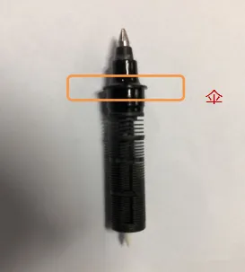
Regulator component: Observe that the regulator component belt is a structural feature similar to an “umbrella” with a low center of gravity. If it is placed on a track, the extra circle of the “umbrella” shape will be easily supported in the track, so it can Make full use of this feature, design a set of tracks, the regulator can hang the material, and then use the manipulator to pick it up. During the installation process, it can achieve precise positioning and successfully put the regulator component into the pen holder.

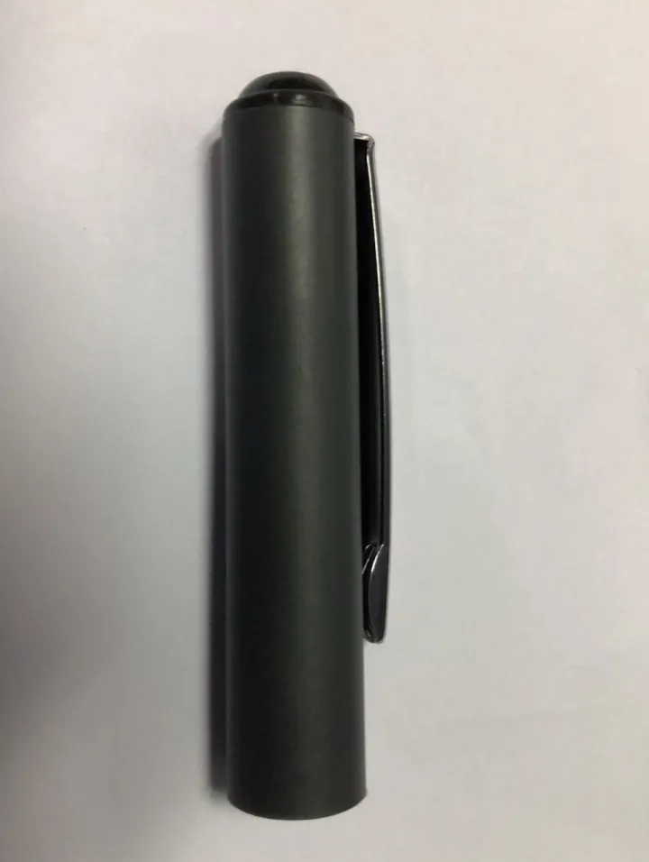
Upper cap assembly: The structure of the upper cap assembly has no characteristics, neither the diameter difference between the two ends, nor the “umbrella” structure, but the characteristic of the upper cap is that one end is the mouth, and the other end is the upper plug without opening. Features, we can use a central shaft, the mouth can be threaded in, but the tail can’t be threaded in. This feature can discharge the upper cap assembly in a fixed direction. In the equipment, add a set of flip positioning system to successfully realize the upper cap. Component installation.

Summary: To realize the equipment assembly of the product, it is necessary to conduct in-depth research on the structural characteristics of the product. The size, shape, center of gravity, etc. are all factors that need to be judged. When one condition is met, the influence of other secondary factors needs to be evaluated. In short, The more obvious the structural characteristics of the components, the easier it is to realize the assembly of the equipment. ◆Motion design: After analyzing the structural characteristics of the product, it is necessary to start the mechanical structure design of the installation of each component, which includes the movement mode, movement curve, movement interference point, etc. Take the assembly of 155 products as an example, Explain the idea of motion design. Pen holder assembly: Due to the difference in size between the two ends of the product, the mouth and tail of the pen holder have been successfully separated. In addition, the weight of the pen holder assembly itself can be analyzed and it can fall vertically into the jig under the action of gravity. Therefore, what we need to design is the vertical slideway of the pen holder, falling into the positioning fixture, etc. The station design is much simpler. Regulator component: As mentioned earlier, using the “umbrella” feature of the regulator, after hanging the discharge, we can design a manipulator at the discharge port of the material channel, and wait with the mouth open. When the signal comes, the manipulator grips the regulator component , and its precise positioning feature ensures that the regulator components are accurately and safely put into the pen holder. What we need to design is a manipulator that meets the size of the regulator components, and an installation positioning system. Upper cap assembly: The discharge feature of the upper cap assembly is that the tail falls downward and needs to be turned over. Therefore, at this station, we need to design a turning mechanism. Summary: In the entire mechanical design, we have used many manipulator structures similar to human hands. This design, due to the manual assembly of profiling, has accurate positioning and single structure, and is superior to manual assembly. In the subsequent mechanical design will be used many times. In addition, its positioning structure is applied to the movement of the cylinder, and this pneumatic auxiliary function is also an important design means in equipment design. Completing the above two steps is the follow-up drawing, parts processing and other work. As for the subsequent assembly and debugging, due to our careful research on product structure characteristics and reasonable design methods such as action structure, the assembly and debugging of equipment will be easy. Very easily, it was only a matter of time before the equipment went into production.
